
The Basic Guide of Switch Debouncing
Switches are very important part of machine interface. Pressing horn in your car or hitting the call button on your cell phone, we interact with daily various machines through switches. There are varieties of switches we press, rotate or touch daily. Your funky radio jumps 2 or 3 channels ahead when you press tuning button only once. Sometimes your TV does not respond and you have to press the remote button very hard. Have you seen a counter in mall door advances several digits when only one person is passed through the door? These are classic problems with bad switch debouncing. Novice embedded designers often face issues in switch debounce design. This article is a small introduction to the switch debouncing techniques.
Switches And Mechanical Contact Bouncing
Interfacing a switch with microcontroller looks very simple thing; but a lot of things happen behind the scene when a user presses a button. Understanding the behaviour of switches helps in designing a good switch debouncing policy.
When the contacts of a mechanical switch are pressed, they rebound several times with different frequencies and then settle down to a fixed state. The rebound of mechanical contact is known as bounce. We have variety of switches; push buttons, SPDT, DPDT, latch-able buttons, rotary switches, joysticks etc. Again these switches come in different size and different current ratings. Because of such variations in switches, the bounce is also different in each type of switches. People press buttons in different ways. Some people press buttons very quickly, some push it very slowly, some use do it by hand, some use different objects to reach to the switches. So the designing the debouncing solution could be tricky sometimes.
How To Get Rid of Switch Bounce
What type of switch you choose is mainly depends on the application needs. Once you know the bounce timing stats of a particular switch, you can easily design switch debouncing policy. First crucial step is to find Maximum bounce time of switch contacts. One can observe voltage levels at the switch contacts using oscilloscope and can easily find maximum bounce time. Operate switch with different techniques, slow, fast, with soft touch, with hard touch, release gently, release fast. Try different combinations of these techniques and collect the bounce statistics. With this statistics you can easily arrive at the Maximum bounce time for your switches. Bounce time during open to close transition of switch can be different than the bounce time during close to open transition.
There are some proven techniques used to remove the effect of switch bounce in digital applications. You can use hardware or software switch debouncing methods. Hardware switch debouncing consists of simple hardware filters, digital switch debouncing circuits and dedicated ICs. Software switch debouncing method utilizes different algorithms, some are microcontroller platform dependent using specific interrupts, some use counters and some use simple delays before re-sampling the inputs.
Hardware solutions
Simple RC filter
Most common type of the switches used in small appliances are single throw buttons, tactile push button and board mounted plates. Using a simple RC filter circuit is a lot cheaper solution than any other hardware debouncing technique. Low pass RC filter removes high frequency changes in the switch bounce.
 RC debounce circuit
When the switch is open the voltage across capacitor C rises at a rate determined by values of R1, R2 and C. Bouncing of the switch slows down the charging rate of capacitor C. In time the capacitor charge and the output of the NOT gate (Schimtt trigger) gives logical zero output.
When the switch is closed the capacitor starts discharging via R2. Till the time the capacitor is discharged to a significant level, NOT gate sees logical one at its input. Once the switch settled in stable closed position after bouncing the capacitor C discharges completely and reach level zero. And the NOT gate gives logical one output.
Values of resistors in RC filter
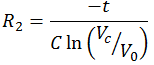
Consider discharging cycle of the capacitor C,
![]()
Where
Vc= Voltage across capacitor C at time t
V0= initial voltage across capacitor C
t = time in seconds
To calculate R2, select Vc such that it is greater than switching voltage of the NOT gate in the above circuit.
So the equation for R2 will become
Now consider charging cycle of capacitor C.
Let R = R1 + R2 then
![]()
Therefore equation for R becomes
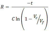
Vf is the final voltage of the charged capacitor. It could be 5V or 3.3V or any other value based on your digital circuit. To calculate R, select Vc such that the less than the lower switching limit for high going signal for NOT gate.
Values of R1 and R2 can be calculated by above formulas.
RC filter with diode
If the value of R is less than R2, then use diode parallel to the R2 as shown in the diagram below so that you can eliminate R2 from the charging path.
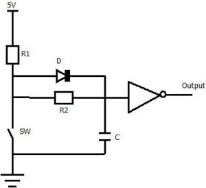 Simple RC Debouncing circuit with diode
SR flip flop latch
SR flip flop latch is very good debouncer for switches with double throw. It consist of 2 NAND gates connected as shown in below diagram.
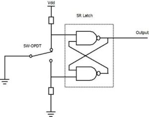 SR Latch used for debounsing SPDT switch input
When we move switch to a position as shown in the diagram above, the output of the latch will be one. If we move the switch to another position, the output of the latch will be zero. When we move the switch between contacts, it bounces little bit on one contact but do not touch the other contact. So we get a stable, bouncing free output from the SR latch.
Switch Debouncing ICs
Since the cheaper alternatives available to fix the bouncing problem, specialized switch debounce ICs are not very popular. Maxim Integrated Products Inc. is the one leading manufacturer of debounce ICS. They have different variants with single, dual and octal switch debouncers in one package. These debouncing ICs provide inbuilt ESD protection.
More information can be found in application note 287.
Handling Switch Debouncing in Software
Basic idea in software debouncing is to sample the input at regular interval and filter out the glitches. There are number of different ways to implement switch debouncing. If you are not much concerned about real time performance just check the switch input state, then wait a bit and recheck again. If the same state is detected then that can be considered as a stable state of the switch. Another way is to use counter and check for how long the switch is low or high and if it is consistently low or high for predefined time then it is considered stable state of switch. Sometimes EMI can produce false signals on the microcontroller pin inputs. Software debouncing also filters such noise.
Programmers must take some care while designing debouncing policy. Avoid sampling of switch input at rate synchronous to other events which can create EMI, e.g. motor direction change frequency or 50Hz/60Hz frequency. Do not connect undebounced switches directly to the interrupt pins of microcontrollers. Some microcontrollers provide special interrupt pins which have inbuilt RC filter. Such pins can be used as switch interrupts.
Hardware debouncing involve some cost of components and also need some space on circuit board. So software debouncing is very popular and people are using different algorithms for implementing switch debouncing.
Author: Mohan Vadnere
Mohan is working in embedded system design since 11 years. In his career Mohan worked in different fields like research and development, consumer electronics, process automation, device driver development and automotive software development. He has hands on experience in hardware design, board bring up and production, software architecture and design. He is passionate about robotics, automation, automotive software development and sensors. He loves talking about control systems, predictive control, embedded software optimization.

Nice article.
Nice article Mohan
Nice One Mohan…
Thanks Gopal.